The post A Guide to the Role of Insulation Monitoring Devices in DC EV Charging Equipment appeared first at EVreporter on EVreporter.
As DC EV charging systems move to higher voltages and faster charging speeds, ensuring electrical safety is becoming increasingly important. In this explainer article, Ian Wiper, Electronics Engineer at Broyce Control, discusses the role of Insulation Monitoring Devices (IMDs) in improving the safety, reliability, and uptime of modern DC EV charging infrastructure.
1. What is an insulation monitoring device?
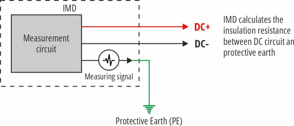
An Insulation Monitoring Device (IMD) is a safety device that continuously monitors the insulation resistance between an isolated high-voltage DC system and protective earth. In a DC fast charger, the output circuit is intentionally designed as an unearthed (IT) system, meaning there is no direct electrical connection between the live DC conductors and protective earth. This arrangement offers several advantages for high-voltage applications, but it also requires continuous supervision of the insulation condition.
The IMD injects a very small measuring signal into the isolated DC system and analyses the response to calculate the insulation resistance between the live conductors and protective earth.
The measuring current is extremely small and does not interfere with the normal operation of the charger. By continuously monitoring the insulation resistance, the IMD can detect deterioration long before it develops into a dangerous fault. If the measured insulation resistance falls below a predefined threshold, the IMD generates an alarm or trip output, allowing the charger controller to inhibit charging or safely disconnect the high-voltage circuit.
Rather than simply detecting faults after they occur, an IMD provides continuous supervision of the electrical insulation throughout the charger’s operational life, helping maintain both safety and reliability.
2. Why is continuous insulation monitoring crucial for DC charging equipment? At what voltage do IMDs see use?
Modern DC fast chargers operate at increasingly higher voltages to reduce charging times and support larger battery capacities. While early chargers typically operated at around 500 VDC, many current platforms operate at 800 VDC or 1000 VDC, with the industry now moving towards 1250 VDC and higher for Megawatt Charging System (MCS) applications.
These chargers operate in demanding environments where moisture, condensation, dust, vibration, thermal cycling and repeated connection and disconnection of charging connectors can all contribute to gradual insulation degradation. Although the charger may continue to function normally, the insulation resistance can slowly reduce over time.
Unlike a production insulation test performed during manufacturing, an IMD continuously monitors the system throughout its entire service life. This enables the charger to detect deteriorating insulation before it develops into a hazardous condition, allowing preventative maintenance to be carried out before an unexpected failure occurs.
As charger voltages continue to increase, continuous insulation monitoring becomes even more critical in maintaining electrical safety, maximising charger availability and protecting both equipment and users.

3. What happens when insulation integrity is compromised?
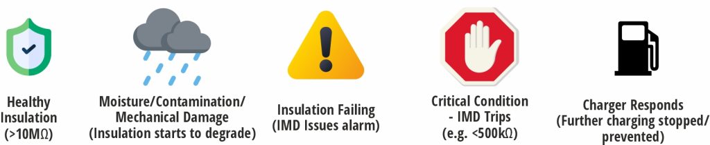
When insulation integrity begins to deteriorate, the resistance between the live DC circuit and protective earth gradually decreases. This creates leakage paths from the high-voltage conductors to the charger enclosure, cable shielding, connector body or other conductive parts connected to protective earth.
Initially, there may be no obvious indication that a problem exists, and the charger may continue to operate normally. However, as the insulation continues to degrade, the risk of electric shock, arcing, equipment damage and nuisance shutdowns increases significantly.
From the IMD’s perspective, this deterioration appears as a gradual reduction in insulation resistance. Once the resistance falls below the configured alarm threshold, the IMD signals the charger controller, allowing appropriate action to be taken. This may include generating a warning, preventing a charging session from starting, or safely disconnecting the high-voltage output if charging is already in progress.
By detecting insulation deterioration at an early stage, the IMD helps prevent faults from developing into unsafe conditions, reducing unplanned downtime and supporting the long-term reliability of the charging infrastructure.
4. Can you explain how insulation monitoring and earth fault detection serve different functions?
Although insulation monitoring and earth fault detection both contribute to electrical safety, they perform fundamentally different functions and should not be considered interchangeable.
An Insulation Monitoring Device (IMD) is predictive. It continuously measures the insulation resistance between the isolated DC circuit and protective earth, allowing it to detect deteriorating insulation before significant leakage current exists. This enables preventative maintenance and allows the charger to respond before the fault develops into a hazardous condition.
Earth fault detection devices, such as residual current monitors (RCMs) or earth leakage relays (ELRs), are reactive. Rather than measuring insulation resistance, they detect current already flowing to earth. By the time an earth fault device operates, a fault path has already been established.
In simple terms:
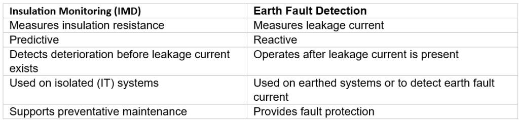
In many EV charging applications, both technologies may be used together, with the IMD providing continuous supervision of insulation health while earth fault detection provides protection against leakage current.
5. What are the early warning signs that an IMD catches?
One of the greatest advantages of an IMD is its ability to detect gradual deterioration in insulation long before conventional protection devices recognise a problem.
Typical causes of insulation degradation include:
- Moisture ingress into charging cables or connectors
- Condensation forming inside enclosures
- Ageing or cracked cable insulation
- Damage caused during installation or maintenance
- Conductive dust or contamination
- Wear within the charging connector
- Thermal cycling and repeated heating and cooling
- Mechanical vibration
- Coolant ingress in liquid-cooled charging systems
Many of these conditions initially reduce insulation resistance without creating sufficient leakage current to operate an earth fault or residual current device. From an operator’s perspective, the charger may appear to function normally even though the insulation is gradually deteriorating.
Because an IMD continuously monitors insulation resistance, it detects these changes at an early stage. This allows maintenance to be planned before the charger experiences an unexpected shutdown or develops into a more serious safety issue.
For Charge Point Operators (CPOs), this predictive approach reduces emergency call-outs, improves charger availability and helps protect charging revenue by minimising unplanned downtime.

6. International standards such as IEC 61557-8 and UL 2231 set requirements for insulation monitoring in EV charging. How well understood are these standards?
Awareness of insulation monitoring requirements has improved considerably over the past few years, particularly among established charger manufacturers developing products for international markets. However, there are still some common misconceptions.
One of the most frequent misconceptions is that selecting an IMD is simply a matter of choosing a device with an appropriate voltage rating. While voltage capability is important, it is only one part of the overall selection process.
Charger manufacturers should also consider:
- Compliance with relevant standards, including IEC 61557-8 and regional requirements safety standards
- Measurement performance and accuracy
- Response characteristics and fail-safe operation
- Communication interfaces such as Modbus RTU or CAN
- Relay outputs and integration with the charger controller
- Ease of commissioning, diagnostics, and long-term technical support
Another important consideration is when the IMD is introduced into the project. Incorporating insulation monitoring early in the charger design process makes certification significantly easier than attempting to integrate it late in development. As charging systems continue to evolve towards higher voltages and greater charging power, insulation monitoring should be viewed as an integral part of the overall electrical safety architecture rather than simply another component required for compliance.
7. At what stage are IMDs integrated? Is retrofit possible?
Ideally, an IMD should be specified during the earliest stages of charger design, as it forms an integral part of the charger’s electrical safety architecture. Incorporating the IMD early allows the high-voltage system, control software, communications and protection strategy to be developed around its operation, making certification and validation significantly more straightforward.
Many charger standards require insulation monitoring to be incorporated as part of the overall safety concept. For example, compliance with IEC 61851-1 and, for North American markets, UL 2231 often requires an appropriate insulation monitoring solution to be correctly integrated into the charger design. Leaving this until late in the development process can lead to unnecessary redesign, additional testing and increased certification costs.
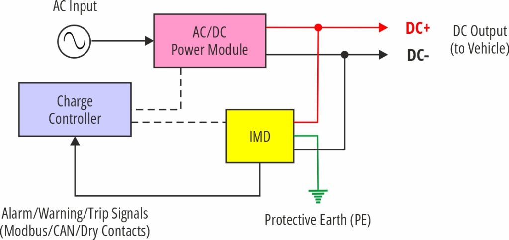
The IMD is typically connected to the isolated high-voltage DC output and interfaces with the charger controller via relay outputs and/or communication protocols such as Modbus RTU or CAN. When an insulation fault is detected, the controller can generate an alarm, inhibit charging, or safely disconnect the high-voltage contactors depending on the manufacturer’s protection strategy.
Retrofitting an IMD into an existing charger can be possible, but it depends on the charger architecture. Factors such as the isolation topology, available space, power supply, controller compatibility and software functionality all need to be considered. Although retrofit can often be achieved successfully, integrating the IMD during the original design phase will always provide the most robust and cost-effective solution.
8. What does a fault event look like from an IMD’s perspective?
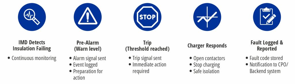
From the IMD’s perspective, a fault event is usually a gradual process rather than an instantaneous failure.
The IMD continuously monitors the insulation resistance between the isolated DC circuit and protective earth. As the insulation begins to deteriorate, the measured resistance gradually decreases. Initially, this reduction may have no visible effect on charger operation, but the IMD continues to monitor the trend.
Once the insulation resistance reaches the configured warning threshold, the IMD can generate an alarm, allowing maintenance personnel or the charger management system to investigate before the condition becomes critical.
If the insulation resistance continues to fall and reaches the trip threshold, the IMD changes state and signals the charger controller.
Depending on the charger manufacturer’s safety strategy, the controller may:
- Prevent a charging session from starting
- Safely stop an active charging session
- Open the high-voltage contactors
- Record the fault within the charger diagnostics
- Notify a remote monitoring platform or maintenance team
This controlled sequence ensures that the charger responds safely and predictably, reducing the risk of equipment damage or unsafe operating conditions.
A typical sequence is:
1. Healthy insulation
2. Gradual insulation degradation
3. IMD detects falling insulation resistance
4. Warning threshold reached
5. Trip threshold reached
6. Charger controller responds
7. Charging inhibited or safely disconnected
8. Maintenance carried out before returning the charger to service
9. What should charger manufacturers assess when selecting an IMD?
Selecting an IMD involves much more than matching the maximum operating voltage. While voltage capability is an important consideration, it should form part of a broader technical evaluation to ensure the device integrates effectively with the charger and meets both current and future requirements.
Key selection criteria include:
- Maximum operating voltage
- Compliance with IEC 61557-8 and relevant regional standards
- Insulation resistance measurement range
- Measurement accuracy and repeatability
- Response time
- Relay output configuration
- Communication interfaces such as Modbus RTU or CAN
- Ease of commissioning and configuration
- Diagnostic capabilities
- Environmental operating conditions
- Physical size and ease of installation
- Availability of long-term technical support
Procurement teams often focus on initial purchase price and voltage rating while overlooking factors that can significantly affect the total cost of ownership. A device that offers better diagnostics, simpler integration and comprehensive technical support can substantially reduce engineering time, commissioning effort and future maintenance costs.
It is also important to consider future scalability. As charging infrastructure continues to evolve towards higher voltages and higher power levels, selecting an IMD that can support future charger platforms can avoid costly redesigns later in the product lifecycle.
10. How do EV charging safety requirements differ from traditional industrial applications?
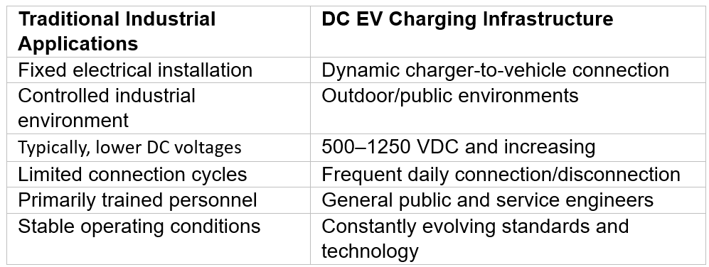
Many of the fundamental principles of electrical protection remain the same: identify unsafe conditions, protect people and equipment, and maintain reliable operation. However, EV charging introduces a number of additional challenges that make electrical safety considerably more demanding than many traditional industrial applications.
- Unlike fixed industrial equipment, EV chargers operate in public or semi-public environments where they are used by people with little or no electrical knowledge. Safety systems must therefore protect both trained service engineers and everyday users.
- DC fast chargers also operate at significantly higher voltages and power levels than many conventional industrial control systems. Modern charging infrastructure is rapidly evolving from 500 VDC platforms to 800 VDC, 1000 VDC and now 1250 VDC systems supporting Megawatt Charging Systems (MCS). As voltage levels increase, maintaining insulation integrity becomes increasingly important.
- Another key difference is that the electrical system changes every time a vehicle is connected. The charger, charging cable, connector and vehicle battery effectively become one high-voltage system during a charging session. This creates a dynamic operating environment that places greater demands on monitoring and protection than many fixed industrial installations.
- In addition, EV chargers are exposed to a wide range of environmental conditions, including rain, condensation, dust, vibration and repeated connection cycles, all of which can contribute to insulation degradation over time.
11. What is the one thing about insulation monitoring that you wish more people understood?
The biggest misconception is that an Insulation Monitoring Device is simply another component required to satisfy a standard. In reality, it is a key contributor to charger safety, reliability and long-term operational performance.
An IMD does far more than identify faults. By continuously monitoring insulation resistance, it provides early warning of deterioration before it develops into an unsafe condition or causes an unexpected charger outage. This enables maintenance to be planned rather than reacting to failures after they occur. For Charge Point Operators (CPOs), this has significant commercial benefits. Every charger that is unexpectedly taken out of service represents lost charging revenue, increased maintenance costs and a poorer customer experience. By identifying insulation issues at an early stage, IMDs help maximise charger availability, reduce emergency call-outs and improve network reliability.
As EV charging infrastructure continues to expand and charging power increases, the industry’s focus is moving beyond compliance towards operational resilience. Charger manufacturers and operators are increasingly looking for solutions that not only satisfy safety standards but also improve uptime, simplify maintenance and reduce lifetime operating costs.
Ultimately, effective insulation monitoring should be viewed as an investment rather than an obligation. It protects people, safeguards valuable equipment, supports compliance with international standards and helps ensure that charging infrastructure remains safe, reliable and available throughout its operational life.
“The best insulation monitoring systems are those that identify problems long before drivers ever experience them.“
About Broyce Control’s Insulation Monitoring Solutions
Building on more than 60 years of experience in electrical protection and monitoring, Broyce Control offers a range of insulation monitoring devices specifically developed for high-voltage DC applications, including EV charging infrastructure. The IMD100 provides continuous insulation monitoring for isolated DC systems up to 1000 VDC and has been widely adopted by charger manufacturers seeking a reliable, standards-compliant solution. Complementing this is the new IMD125, designed for systems up to 1250 VDC to support the latest generation of high-power and Megawatt Charging System (MCS) applications. Together, the IMD100 and IMD125 combine continuous insulation monitoring with flexible communications, straightforward system integration and proven reliability, helping OEMs and Charge Point Operators deliver safer, more dependable and future-ready EV charging infrastructure.
Further information is available here: https://renewableenergyprotection.com/insulation-monitoring/
Also read: EV charger manufacturer Zenergize raises USD 2 million in seed round
Subscribe & Stay Informed
Subscribe today for free and stay on top of latest developments in EV domain.
The post A Guide to the Role of Insulation Monitoring Devices in DC EV Charging Equipment appeared first at EVreporter on EVreporter.
Source link